
Before I could build my voltage regulator, I was instructed to design a circuit for my LED tree, so I could measure how much power it needed. Initially, when I decided to do an LED tree, inspired by this project: https://hackaday.io/project/162840-rgb-tree
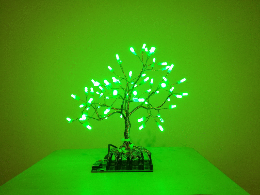
I didn’t think the circuitry behind it would be too complicated, and I would just need to do loads of repeating basic LED circuits. But I hadn’t considered the amount of current each LED requires, as well as the Arduino’s limited number of data pins.
Because of this issue, I was guided into looking at charlieplexing, a method of controlling large numbers of LEDs from 1 data pin. And although I could understand how it worked on a basic level, it seemed too complicated for the time I had left. Instead, I decided to scale back on the number of LEDs/ branches my tree would have and run 2 LEDs in series for each data pin.
This set me on designing my protoboard. After a lot of iteration, I settled on a design that would allow for a maximum of 18 LEDs. I then realised how much soldering my design would require, and my soldering skills/speed did not match the time I had, so I would have to scale back even further.
With this project, I think I have bitten off more than I can chew for the time I have. I hope I manage to complete it, though on a much smaller scale, and still make it look pretty. This has taught me that I need to consider timeframes more in projects, so I can manage my expectations better.